|
| Most of my synthesizers are boring DSP-based
digital stuff that cannot be easily tampered with. However, one piece
in my setup is at least partly analogue: the Kawai K3m. It has 6
voices, each with a dual DCO, a VCF and a VCA. It's rather obvious
what part of the synthesizer is plain boring and what could actually
be fun to abuse.
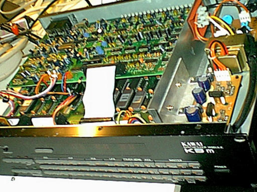
Since the K3m is controlled by a microprocessor (which, by
definition, therefore is rather boring to mess around with) I saw no
point in trying to make the K3m into a 6-channel LP-filterbank (since
that would mean having to alter the software), but instead decided to
turn it into a 1-channel 6-peak LP-filterbank. |
 |
|
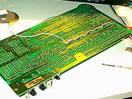
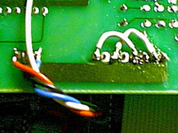
| The first problem was to find where to feed the
signal, but after some measuring I found out that feeding the signal
through a 47 kOhm resistor to the positive input of the filter (pin 1
on the SSM2044), it got beautifully mixed with the original signal
from the two oscillators. After soldering the resistors into place on
the back side of the PCB, I simply connected them to each other with a
wire. |
 |
|
| The first try! Temporarily connecting the resistors
directly to an effect send on my mixer, the synthesizer back to one
of the mixer channels, MIDI to a keyboard and feeding my Alesis drum
machine through the setup while madly hammering on the keyboard gave
this result. Not bad for a first try. |
 |
|
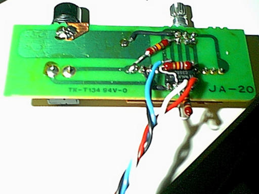
| Now I just needed a jack for the input. I've never
had any usage for the head phone output, so rather than either drill a
hole in the front and adding a jack that looks completely out of place
or adding the jack on the back where it's out of reach, I decided to
modify the head phone pcb to fit my needs. As a bonus, this PCB comes
with a volume knob and all!
The construction is quite simplistic. I use a 358 dual amplifier
(simply because it was the best I had lying around, otherwise I'd
probably have used a 072 instead) and feed the input signal to the
negative input of one of the amplifiers through a 18 kOhm resistor,
using one channel of the existing 50 kOhm volume knob as feedback.
Then I feed the output to the othre amplifier which also is used as an
inverting amplifier using two 18 kOhm resistors. The two positive
inputs of the amplifiers are grounded, naturally. |
 |
|
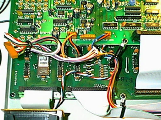
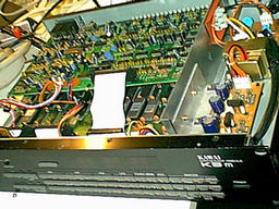
| Here is a close up of the main PCB where you can
see the cords from the input PCB (the former head phone PCB) connected
to +15 Volt (red), -15 Volt (blue), ground (black) and further to the
resistors connected to the filters (white). Please note the patch on
the now unused head phone connector. It's essential since the volume
knob on the front also controls the volume of the line out in the
back, so without this patch there will be no sound. |
 |
|
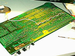
| Here's an angle from the component side with all
connectors in place. I always prefer to modify things in a way so that
they will be possible to reverse if I find out that my modifications
have serious flaws, hence I've strapped up the old head phone cable
like this rather than just simply cut unused wires and remove it
entirely.
Now that I know that it works just perfectly and thus won't even
consider reversing it I might get rid of the remains if I ever get a
reason to do more alterations. |
 |
|
So, it's quite simple. The worst part was to find out what to do,
not to do it. If you know how to wield your soldering iron, go for
it!